
VANGUARD
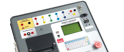
EZCT-2000C (Current Transformer Tester(2,000Vac) with insulation and burden calculation capabilities)
-
- EZCT-2000C
- : Current Transformer Tester(2,000Vac) with insulation and burden calculation capabilities
Excitation Test
The CT excitation test is performed using the ANSI/IEEE C57.13.1, IEC 60044-1 test method.
The test voltage range for the CT excitation test (50 Vac, 300 Vac, 500 Vac, 1200 Vac or 2000 Vac) can be selected, and then the testvoltage is raised and lowered automatically by the EZCT-2000C.
The excitation test voltage and current data is collected and stored in the unit’s internal memory. Any of the 10 possible combinations of X1 to X5 can be tested since all of the unit’s test leads can be connected to all of the CT output terminals at the same time.
Up to 10 excitation tests can be stored in one record.
Once the test is completed, test results can be printed and excitation curves can be plotted on the built-in 4.5-inch wide thermal printer.
Demagnetization
The EZCT-2000C Plus automatically demagnetizes the CT under test when performing an excitation test.
CT Winding Resistance Test
The EZCT-2000C can also measure the DC resistance of the CT winding under test.
The DC winding resistance measuring range is from 100 micro-ohms to 10 ohms.
CT Winding Insulation Resistance Test Feature
The EZCT-2000C Plus offers an IR test feature that can also measure the insulation resistance of the CT’s secondary winding using a test voltage up to 1000 Vdc. The DC winding resistance reading range is from 2 to 500 Mega-ohms.
The insulation resistance test results are displayed and printed on the report.
CT Ratio and Polarity Tests
The EZCT-2000C determines the CT current-ratio using the ANSI/IEEE C57.12.90 measurement method.
A test voltage is applied on any two terminals of the CT (X1 to X5), and the induced voltage is measured through the CT’s H1 and H2 terminals.
The CT current-ratio is displayed on the screen and stored in memory.
The current ratio measuring range is from 0.8 to 5,000 to 1.
The CT winding polarity is displayed as a “+”sign (in-phase) or a “-” sign (out-of-phase) and is annotated with the phase angle in degrees.
CT Burden Test
The EZCT-2000C Plus can measure the CT’s actual connected burden by injecting a 1A or 5A test current into the load.
The CT burden measurements (Voltage, current, Cos φ, and burden impedance) are displayed on the screen and printed on the test report.
This important test verifi es the actual CT measured burden before putting the CT in service, thus avoiding any potential confi guration confl icts.
Documentation
- Model EZCT-2000C User Manual
- Download PDF(4KB)*
- Model EZCT-2000C Data Sheet
- Download PDF(1MB)*